Hardware Hacking - Root UART Shells on GL-AR750
About The Project
Continuing from Arch Cloud Labs TrendNet 731BR router hacking blog post tearing apart firmware, we’ll now start poking at router hardware! The primary objective is to grow my skills in the embedded security domain for DEF CON’s IoT and Embedded Security Villages next year. This weekend’s project focused on a GL-AR750. I originally bought this router in 2017 as a travel router, and it has been collecting dust in my closet for quite some time. What better way to e-cycle than to look at ways to pwn the hardware lying around the house?
This blog post will cover identifying UART headers, leveraging a USB-to-TTL device for serial communications, and ultimately getting a root shell on the GL-AR750 travel router. Let’s get started!
Quick Rundown on UART Identification
Universal Asynchronous Receiver / Transmitter (UART) is a serial protocol for exchanging data between two devices. This is a popular protocol on a significant amount of embedded devices. Per No Starch Press’ “Practical IoT Hacking”,
The Universal Asynchronous Receiver-Transmitter (UART) is one of the simplest serial protocols, and its exploitation provides one of the easiest ways to gain access to IoT devices. Vendors typically use it for debugging.
I’m new to hardware hacking. I bought Practical IoT Hacking and The Hardware Hacking Book from No Starch Press to deepen my understanding of the field, but if you’re a visual learner, I cannot recommend The Flashback Team’s YouTube channel enough. The best breakdown and walk-through tutorial on identifying UART pins on a hardware device, decoding digital signals to identify the baud rate, and more can be seen in The Flashback Team’s “Hacker’s Guide to UART Root Shells”. I highly recommend watching this video to understand how to use a multimeter to identify the voltage (VCC), receiver (RX), transmit (TX), and ground (GND) pin layout for UART. For those looking for a quick synopsis of identification of UART on a device, Secure Ideas breaks down the process of UART pin identification with a multimeter as follows:
-
For ground, identify a 0.0 reading with the black probe on a metal part of the board/case, and the red probe touching the suspected UART pins.
-
For VCC, identify either a constant read of 3.3 or 5 volts.
-
For transmit (TX) identify a floating point value being transmitted on the multi-meter.
-
And finally, through a process of elimination, you should find the receive (RX) pin.
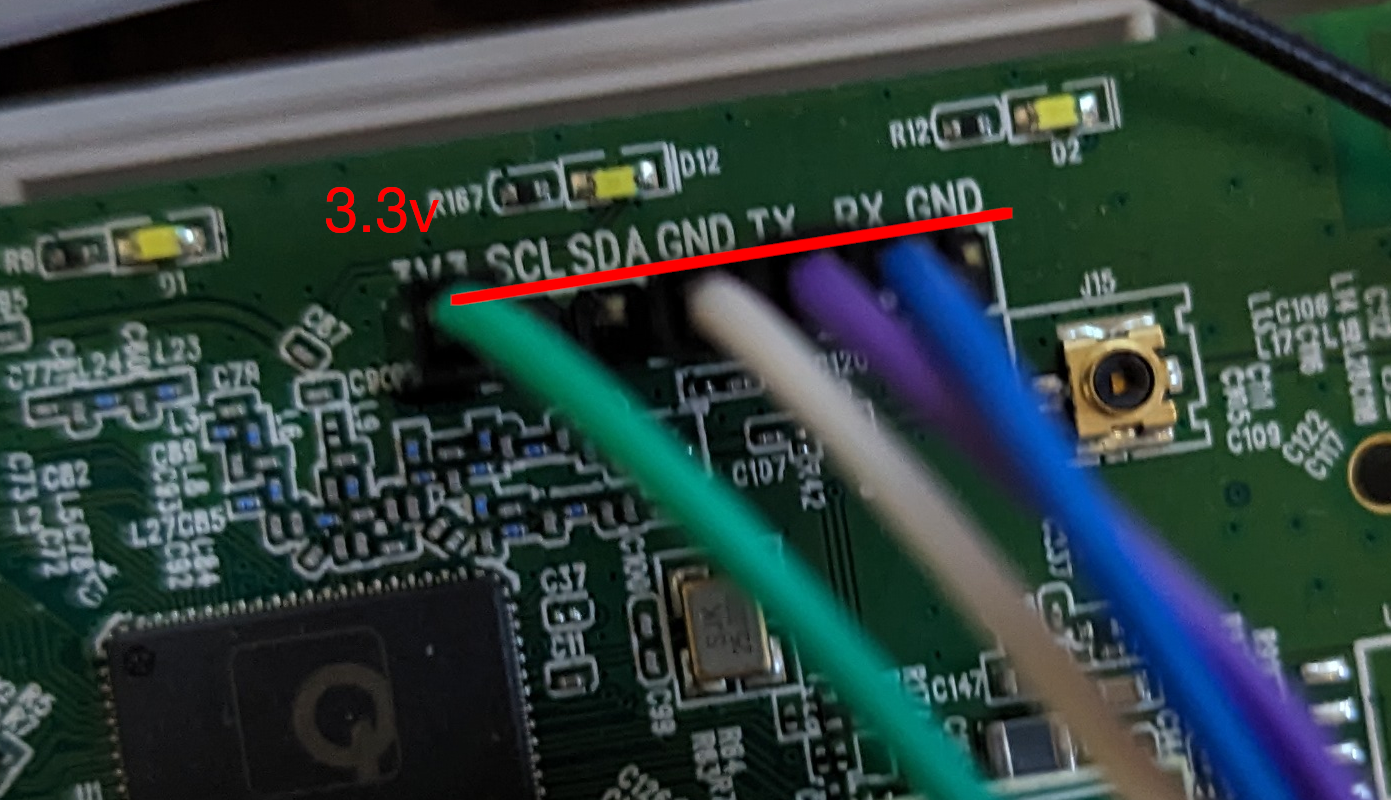
Of course, none of this matters if the UART connection is clearly labeled. This was the case with the GL-Net router! The image below shows header pins already soldered onto the GL-Net board.
Identifying Baud Rate
With the pinout identified, the next step is determining the rate at which data is transferred. This data transfer rate is known as the baud rate. The previously mentioned Flashback Team YouTube video also shows how to identify this with a logic analyzer. However, there are a handful of default values that can be used in a “brute force” fashion to identify the baud rate used by the target device. Additionally, poking at official documentation may have an indication of what the baud rate is. In the case of the target router, official documentation specified the baud rate being 9600.
Plug & Pwn
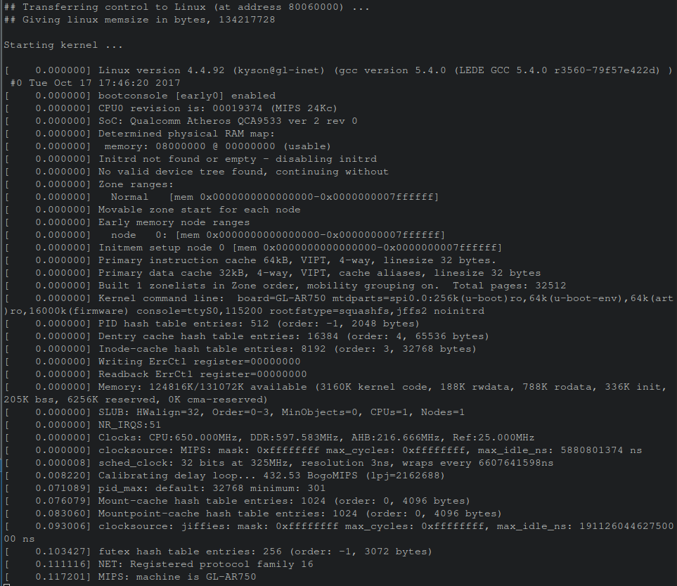
Now, connecting the UART pins to a USB TTL-to-Serial device, one an access this serial console via a utility such as minicom or screen. Executing screen /dev/ttyUSB0 9600 results in a terminal showing a successful console session obtained with kernel boot logs being displayed from the GL-AR750 router!
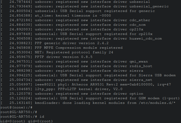
After booting finished, hitting enter resulted in immediately being presented with a root shell!
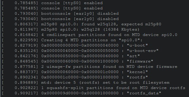
The Value of Console Logs - Memory Maps
In this scenario, a shell was obtained quickly, but what if that didn’t happen? Say a complex password was present on this console. How can the output be leveraged for continued research? Within the boot logs a message containing the memory map of the firmware was displayed. This helps in precisely parsing out the file system from the firmware in the event a tool like binwalk failed.
Why would binwalk fail?
Binwalk relies on magic values to detect files and file systems to parse. In the event data was obfuscated, encrypted or otherwise modified, it would be easy to fool binwalk into not automatically extracting firmware as seen in the previous Arch Cloud Labs blog post.
For example, dd can be used to go to a specific offset within a file and then carve out N-number of bytes. This can be achieved as follows:
# assuming the shell is /bin/bash
# Wrapping a hex-number with `$(())` will convert the hexadecimal value to an integer automatically in bash. A

$> dd if=FIRMWARE.bin of=filesystem.squashfs skip=$((0x60000)) count=$((0x1000000)) bs=1
After parsing out the specific partitions of interest, you can go on and poke at the parsed out filesystem.
Conclusion
This was my first venture into hardware hacking for embedded devices. I always thought hardware hacking had an expensive cost to entry, but with this simple UART example and old inexpensive router, it was trivial to dive into this field via a $13 USD USB-to-TTL device. The continued growth of IoT devices and edge computing will be dominated by a mix of Linux systems and odd-kubernetes systems. I look forward to continuing to grow technical skills in this arena to poke at weird home devices.
Thank you for reading, please consider sharing if this was useful!